
* Following World War 2, there was considerable interest in vertical take-off aircraft, with one branch of research in the field focusing on machines with tilting rotors, props, or ducted fans; and on machines with tilting wings. This document provides a history and description of pioneering tiltrotors, tiltducts, and tiltwings.
* After decades of tinkering, the first workable helicopters emerged from the mid-1930s -- the pioneer being generally recognized as the "Focke-Achgelis Fa 61", designed by Heinrich Focke and Gerd Achgelis, which performed its initial flight in 1936. It was a single-seat machine, with a three-bladed rotor on a truss assembly to each side -- the side-by-side rotor scheme being generally characteristic of later Focke-Achgelis helicopters as well.
In parallel with the work on helicopters, designers were also imagining concepts for hybrids of helicopters and fixed-wing aircraft -- the idea that they could take off and land vertically, while having the performance and range of a conventional fixed wing aircraft. In later times, such aircraft would be known as vertical "take-off / landing (VTOL)" machines.
Focke and Achgelis were one of the first to attempt to build a VTOL machine, working on a fighter designated the "Fa 269" from 1941. The Fa 269 looked generally a conventional aircraft, with a pod outboard on each wing featuring a three-bladed pusher propeller at the rear. The rotors were to be driven via driveshafts by a BMW 801 radial engine, fitted in the fuselage behind the cockpit. For take-offs and landing, the rotors pivoted downward from the wing, with very long main landing gear giving them ground clearance.
Length of the Fa 269 design was 8.93 meters (29 feet 3 inches), with a wingspan of 10 meters (32 feet 9 inches); projected top speed was about 570 KPH (350 MPH / 310 KT). Armament was to be twin short-barreled MK 108 30-millimeter cannon. Development work was performed on subsystems, along with wind-tunnel tests of models and the construction of a mockup. The decline of the German Reich's fortunes in 1944 meant no Fa 269 prototype was ever flown.
In the postwar period, the German Dornier firm did implement Focke's "tiltrotor" concept, building two "Do 29" demonstrators, derived from the Do 27 short-field utility aircraft. They featured a revised forward fuselage with a helicopter-like cockpit; twin Lycoming GO-480-B1A6 flat-six air-cooled piston engines, one in a nacelle under each wing; three-bladed pusher props driven by the Lycoming engines, the props able to hinge down 90 degrees; and tall fixed "taildragger" landing gear.
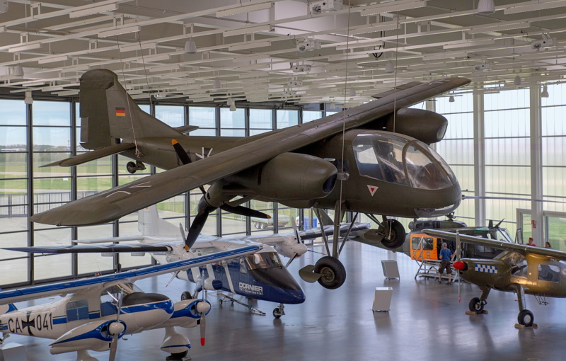
Length of the Do 29 was 9.5 meters (31 feet 2 inches), wingspan was 13.2 meters (43 feet 4 inches), and empty weight was 2,180 kilograms (4,805 pounds). Initial flight was on 12 December 1958. The Do 29s demonstrated outstanding short-field performance, even though the props were never tilted below 60 degrees from the horizontal. However, Dornier did nothing more with the idea after the end of Do 29 flight tests. One remains on display in Germany.
* The tiltrotor concept was more or less obvious, with work going on in the USA. The Platt-LePage company, a pioneer in American rotorcraft design, did patent a tiltrotor design, the "PL-16", but it was still a paper project when Platt-LePage went broke in 1946.
The next year, 1947, the Transcendental Aircraft Company was founded in New Castle, Delaware by Mario Guerrieri and Bob Lichten, previously of Kellet Aircraft -- which had manufactured autogyros, and done research on helicopters. Guerrieri and Lichten had been tinkering with tiltrotor designs since 1945, with Transcendental working on getting their "Model 1-G" single-seat demonstrator into the air.
After suffering through troubles with development and limited funding, the Model 1-G made its initial (tethered) flight on 15 June 1954. It was powered by a Lycoming O-290-A flat-four air-cooled engine mounted in the fuselage, providing 120 kW (160 HP), and turning three-blade rotors at each wingtip, via a driveshaft. Each rotor could be tilted using an electric drive. The aircraft featured fixed tricycle landing gear. The Model 1-G was 7.9 meters (26 feet) long, had a wingspan of 6.4 meters (21 feet), and a rotor diameter of 5.2 meters (17 feet).
The Model 1-G graduated to free flights, with the forward tilt angle gradually being increased to 75 degrees. Unfortunately, the demonstrator suffered a control system failure on 20 July 1955, to crash into the Delaware River. The pilot was unharmed, but the Model 1-G was a loss. It had performed a hundred flights, chalking up 20 hours of flight time. Another demonstrator, the two-seat "Model 2", was built and flown in 1956, with notions of going on to a turboshaft-powered "Model 3". However, funding continued to be a problem, and the work was abandoned in 1957. Transcendental was bought up by Republic Aircraft.
* Bob Lichten had left Transcendental in 1948, to end up at Bell Aircraft, where he continued his work on tiltrotors. In 1951, the US Army Transportation Command had awarded contracts to a number of aircraft manufacturers for the development of innovative rotorcraft demonstrators, with Bell then proceeding on development of the "Model 200" tiltrotor demonstrator, with two to be built. The first, with the service designation of "XV-3" (later "XV-3A", though that designation is not used here) performed its initial flight on 11 August 1955.
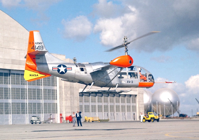
The XV-3 had a fuselage like that of a conventional helicopter, with a glassed-in nose and landing skids, but it had a full tail assembly and wings, with a three-bladed rotor at each wingtip, tilted via electric drive. The landing skids had fluid shock absorbers, and small wheels to allow the machine to be rolled on smooth surfaces. It was powered by a single Pratt & Whitney (PW) R-985-AN-1 Wasp Junior nine-cylinder air-cooled radial engine, providing 335 kW (450 HP); the engine was mounted in the fuselage, with a noticeable curved intake on top of the fuselage, turning the rotors via driveshafts. The control layout mixed features of those of a helicopter and a fixed-wing aircraft, with the rotor tilt controlled by a switch setting.
   ___________________________________________________________________

   BELL MODEL 200 / XV-3:
   ___________________________________________________________________

   wingspan:
     9.5 meters (31 feet 4 inches)
   wing area:
     10.8 sq_meters (116 sq_feet)
   length:
     9.2 meters (30 feet 4 inches)
   height:
     4 meters (13 feet 3 inches)

   empty weight:
     1,905 kilograms (4,205 pounds)
   max loaded weight:
     2,220 kilograms (4,890 pounds)

   max speed at altitude:
     300 KPH (185 MPH / 160 KT)
   cruise speed:
     270 KPH (165 MPH / 145 KT)
   service ceiling:
     4,600 meters (15,000 feet)
   range:
     410 kilometers (255 MI / 220 NMI)

   ___________________________________________________________________
The XV-3 was put through its paces, with careful and tentative attempts to tilt the rotors forward -- which had a nasty tendency to set up rotor instability. On 25 October 1956, test pilot Dick Stansbury moved the rotors to 17 degrees forward of vertical, the machine then going into such a bad case of the shakes that Stansbury blacked out, and the machine landed very hard. Stansbury was badly injured, while the XV-3 was damaged beyond repair.
The second XV-3 moved up to take its place. It differed from the first by having two-blade rotors instead of three-blade rotors, with the rotors in wingtip pod fairings, and also featured a dorsal fin under the tail. It's not entirely certain when all these features were added; experimental prototype configuration tends to be a moving target. Following wind tunnel testing, the second XV-3 began flight tests on 21 January 1958.
By May, the rotor tilt had been pushed to 40 degrees from the vertical, with the result being another fit of instability; the XV-3 was grounded, to be returned to wind tunnel tests. As a result of the tests, the rotor diameter was trimmed, the wing was strengthened, and the rotor controls were stiffened. After returning to flight tests on 12 December, on 18 December Bell test pilot Bill Quinlan became the first person to perform a full conversion from vertical to horizontal flight in a tiltrotor.
The US National Aeronautics & Space Administration (NASA) became involved in test flights -- the wind tunnel tests had been performed in a NASA wind tunnel -- with trials performed into 1966, when a wind tunnel test led to rotor failure, with serious damage to the wind tunnel and the XV-3. That was the end of the XV-3 program. While nothing resembling a practical flying machine, it had proven a very useful test fixture, validating the practicality of tiltrotors. It had performed 250 flights and accumulated 125 flight hours, with flight transitions becoming routine.
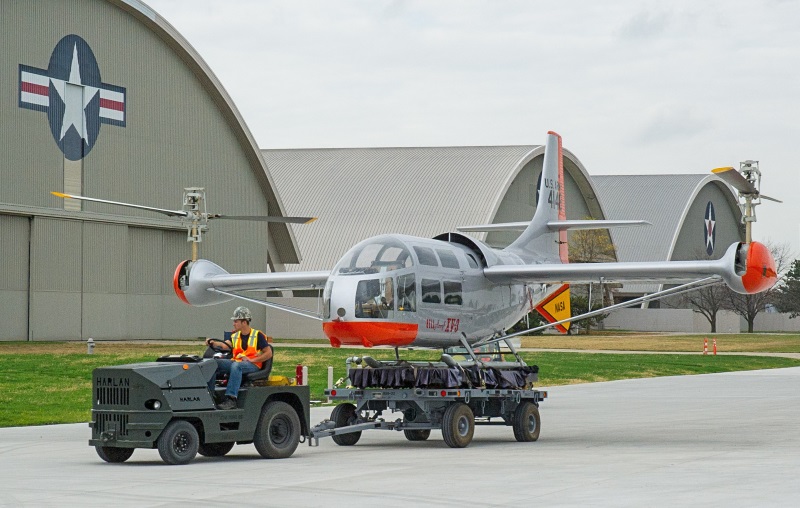
Bell went on to build the much more refined "XV-15" demonstrator, which led directly to the modern Bell-Boeing V-22 Osprey tiltrotor transport. The surviving XV-3 was sent to the "boneyard" at Davis-Monthan Air Force Base (AFB) in Arizona in 1966, to later end up in storage at the Army Aviation Museum at Fort Rucker, Alabama. Bell obtained the machine in 2004, to restore it to display condition, with the XV-3 put on display at the US Air Force Museum at Wright-Patterson AFB in 2007, where it remains today.
* While Bell was putting the XV-3 through its paces, the Curtiss-Wright company was also tinkering with the tiltrotor concept, developing an "X-100" demonstrator from 1957. It was a two-seat aircraft, built of aircraft aluminum along with some fabric over tubing, taildragger landing gear, and a tee tail. It was powered by a Lycoming YT53 turboshaft, fed by an intake on the back of the aircraft behind the cockpit. The engine drove tilting rotors at the wingtips -- or more precisely "tiltprops", each with three short blades featuring a wide chord and a strong twist. The engine exhaust in the tail was fitted with a "jetavator", using doors to deflect the exhaust to control pitch and yaw.
The first free hover flight of the X-100 was on 15 September 1959. After evaluation by Curtiss-Wright, it was passed on to NASA for further flight tests, finally being damaged on 5 October 1961. The damage was limited, but the demonstrator had served its purpose, having accumulated 14 hours of flight time, so there was no interest in fixing it. The X-100 ended up in the hands of the Smithsonian National Air & Space Museum (NASM). At last notice, it was still in storage.
The main reason there was no interest in fixing the X-100 was because Curtiss-Wright was working on a much more ambitious "quad tiltprop" VTOL machine, the "X-200" AKA "M-200", with two prototypes to be built. The project was originally based on company funding, but Curtiss-Wright officials managed to hook the effort up to the "Tri-Service VTOL Program (TSVP)", which was a joint US Air Force, Army, and Navy program office focused on developing VTOL machines for military needs. The X-200 acquired the service designation of "X-19".
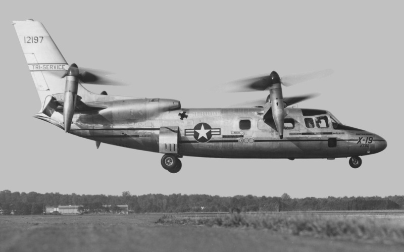
The first prototype was ready for test flights by the fall of 1963. The X-19 had been originally conceived as a four-seat passenger transport, and it accordingly had a fuselage like that of an executive prop aircraft, with a swept tailfin, a set of rectangular wings fore and aft, a tiltprop pod on each wingtip, and tricycle landing gear. The X-19 was of all-metal construction; it was powered by twin Lycoming T55-L-7 turboshafts with 1,975 skW (2,750 SHP) each, with intakes on the top rear of the aircraft. The tiltprops had "handed" rotation, those on the left turning in the reverse direction to those on the right, to cancel torque.
All landing gear assemblies had single wheels, the nose gear retracting up into a well, the main gear tucking into the rear fuselage. Pitch and roll in hover were achieved by differential variation of blade pitch, while yaw was handled by varying the tiltprop pitch angle. The tailfin had a rudder, while each wing had a single control surface, for control in horizontal flight. The two crew had rocket-boosted ejection seats with "zero-zero" (zero altitude / zero speed) capability if something went badly wrong. Length was 12.83 meters (40 feet 1 inch), forward wingspan was 5.94 meters (19 feet 6 inches), rear wingspan was 6.55 meters (21 feet 6 inches), and empty weight was 4,425 kilograms (9,775 pounds).
Initial hover flight was on 20 November 1963, but the X-19 was reluctant to fly right; it came back to earth quickly and heavily. It was flying again by June 1964, performing horizontal flights, to then attempt to hover again. The machine was very unstable, and so the engineers went back to the drawing board to give the X-19 a stability augmentation system before it was flown again.
The X-19 program, in short, wasn't going well. The effort was underfunded and undermanaged, with the aircraft becoming overweight and not very manageable in the air. Flight tests resumed in early 1965, with further groundings and rework -- up to 25 August 1965, when a transmission element failed during a hover test, leading to a prop failure, with the two crew sensibly and safely punching out.
The X-19 was totaled. It had spent less than four hours in the air. The program was formally abandoned later in 1965. The second prototype was not completed, to be later junked. The X-19 was the last aircraft to be flown by Curtiss-Wright -- once a fine company that had gone into decline during World War II, and never recovered.
BACK_TO_TOP* While work on tiltrotors and tiltprops went ahead, there was also research into "tiltducts" -- just like tiltprops, except that the props were contained in ducts. The advantage of a ducted prop is that it is more efficient, with losses from the prop tips minimized by the duct, and provides more focused thrust. A duct could also provide lift in forward flight; a vane could be placed in the duct exhaust to provide control over the exhaust direction. The disadvantage is that it's a draggier configuration, and so isn't compatible with high speed.
The first tiltduct aircraft to fly was built by Edmund Doak JR, a Douglas Aircraft Company engineer who set up his own firm in Torrance, California, in 1940, the firm working as a subcontractor to aircraft manufacturers. In the early 1950s, Doak began to promote his ideas for a VTOL aircraft. In 1956, the US Army Transportation Research & Engineering Command awarded the Doak firm a contract to develop a single flight demonstrator. The "Doak Model 16" performed its initial flight on 25 February 1958, at the Torrance Municipal Airport.
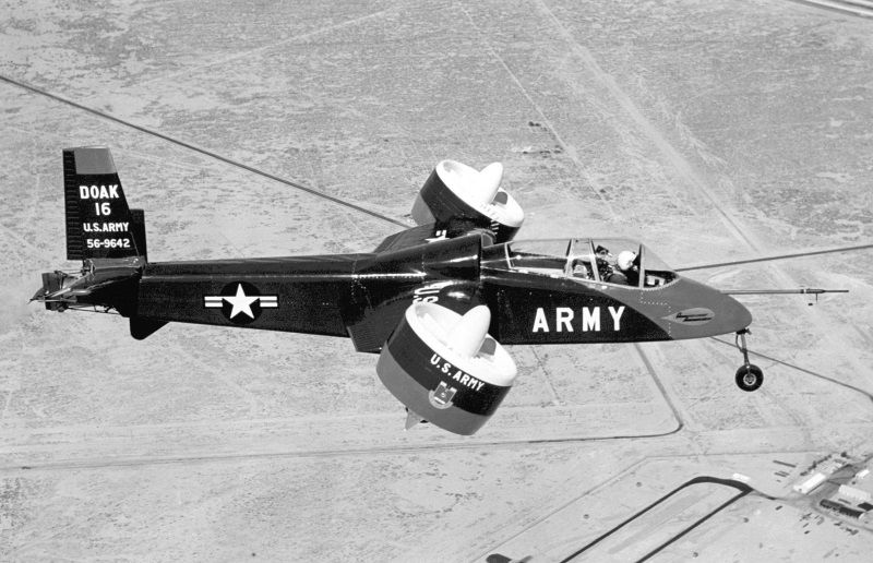
The Doak 16 was a slim aircraft, originally with a fuselage of open steel tubing to save weight, though it was given a fiberglass nose sheath and fuselage aluminum sheathing after the open frame proved aerodynamically troublesome. It featured:
The first transition from vertical flight and back again was on 5 May 1958. The Model 16 had some problems, but none that didn't seem correctable, and was flying fairly well by the summer of 1958.
   ___________________________________________________________________

   DOAK MODEL 16 (VZ-4DA):
   ___________________________________________________________________

   wingspan over ducts:
     7.77 meters (25 feet 6 inches)
   wing area:
     8.92 sq_meters (96 sq_feet)
   length:
     9.75 meters (32 feet)
   height:
     3.05 meters (10 feet)

   empty weight:
     1,045 kilograms (2,300 pounds)
   loaded weight:
     1,450 kilograms (3,200 pounds)

   max speed:
     370 KPH (230 MPH / 200 KT)
   service ceiling:
     1,830 meters (6,000 feet)
   range:
     370 kilometers (230 MI / 200 NMI)

   ___________________________________________________________________
The Doak 16 was passed on to the Army for testing in September 1959, being given the military designation of "VZ-4DA" -- "DA" no doubt standing for "ducted aircraft" -- put through a flight evaluation by NASA. In 1960, the Doak company ran into financial problems, with the Douglas firm taking over the program. While the evaluation went fairly well, the Army decided that the tiltduct scheme didn't offer enough advantage over helicopters, and discontinued the project in 1963. The Doak 16 ended up in the hands of NASA, to ultimately be placed on display in the US Army Transportation Museum at Fort Eustis, Virginia.
* While Bell was working on the XV-3 demonstrator, the company was also investigating tiltduct technology. Studies had begun in 1953, with the company devising a concept for a "D-190" tiltduct for search and rescue (SAR). That didn't happen, but in 1957 the US Navy awarded Bell a study contract for a tiltduct assault transport, leading to a concept proposed to the Navy, with derivative concepts proposed to the Marines and Army. By that time, the number of VTOL projects being investigated by the Pentagon was spiraling, with an "Ad Hoc Committee of VTOL Aircraft" established by the Department of Defense in 1959 to try to sort things out.
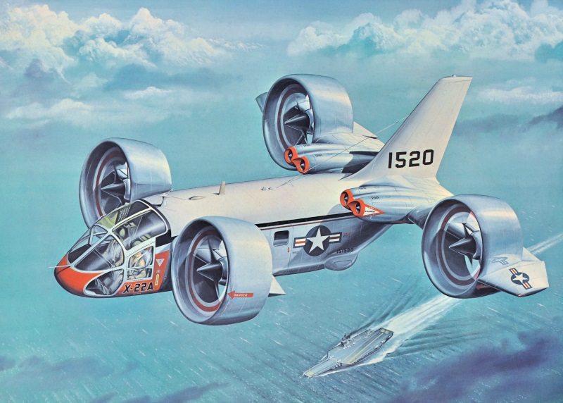
That led to the Tri-Service VTOL Program, mentioned above, with an initial request for proposals in 1961 leading to submissions from a number of manufacturers for VTOL machines. In 1962, Bell was awarded a contract to develop two "X-22A" demonstrators, with the first making its initial flight, in hover, on 25 May 1965. Since there would never be an "X-22B", it's just called "X-22" here.
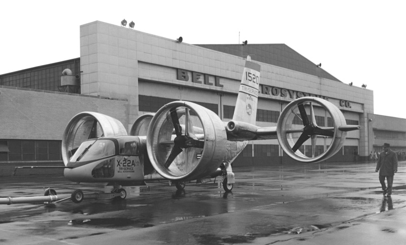
The X-22 was an unorthodox but tidy design, made primarily of aircraft aluminum alloy, with a boxy fuselage and four tiltducts, two forward and two aft. The front tiltducts were mounted on "shoulders" extending from the fuselage, with the rear tiltducts mounted on the ends of short wings. All the ducts had a fixed horizontal airfoil attached to the rear, with the rear ducts also having fixed wingtip airfoil extensions. There was a tall tailfin, with powerplants consisting of two General Electric YT58-GE-8D turboshafts, with 930 kW (1,250 SHP) apiece, mounted inboard and in front of each wing, for a total of four engines. The fans were driven using an array of driveshafts that permitted the aircraft to keep on flying if one engine were lost. There was also a very little prop mounted on top of the tailfin, one might guess for pitch trimming.
The X-22 had tricycle landing gear, the nose gear having twin wheels and retracting backward, the main gear having single wheels and tucking inward into sponsons. Along with two flight crew, with side-by-side seating, the X-22 could carry six passengers.
   ___________________________________________________________________

   BELL X-22:
   ___________________________________________________________________

   front wingspan (over ducts):
     6.98 meters (22 feet 11 inches)
   rear wingspan (over ducts):
     11.96 meters (31 feet 4 inches)
   length:
     12.07 meters (39 feet 7 inches)
   height:
     6.31 meters (20 feet 8 inches)

   empty weight:
     4,735 kilograms (10,478 pounds)
   max loaded weight:
     8,000 kilograms (17,645 pounds)

   max speed:
     410 KPH (255 MPH / 220 KT)
   service ceiling:
     8,500 meters (27,800 feet)
   hover ceiling (in ground effect):
     3,660 meters (12,000 feet)
   hover ceiling (out of ground effect):
     1,830 meters (6,000 feet)
   range:
     715 kilometers (445 MI / 385 NMI)

   ___________________________________________________________________
The tiltducts were tilted hydraulically, all of them in step; the propellers had independent variable pitch to provide yaw control, or roll control in hover flight. The X-22 had a stability augmentation system to help it hover, plus a "variable stability control system" that could be reprogrammed to experiment with flight control parameters. The X-22 also had a pioneering "head up display (HUD)".
After months of flight tests, on 8 August 1965 the first prototype suffered a hydraulic failure that led to a hard landing; the crew were not seriously hurt, but the aircraft was damaged beyond repair. The second prototype got into the air in January 1966, to continue test flights wearing various organizational hats to 1980. It was an extremely successful program, returning a great amount of data on VTOL flight, though there was never any serious consideration of turning it into an operational aircraft. The second prototype is now on display at the Niagara Aerospace Museum in New York State.
* Roughly in parallel with the X-22, the French Nord Aviation firm -- later Aerospatiale -- developed a small tiltduct demonstrator, named the "Nord N500 Cadet". Two were built, the first being used for ground tests, the second performing a tethered hovering flight on 23 July 1968.
The Nord N500 was a minimalist machine, with a pod for a fuselage, for a single pilot who sat on an ejection seat. The pod featured an upraised tail ending in a conventional tail assembly, with twin Allison T63-A-5A turboshafts, providing 235 kW (315 SHP) each, mounted above the tailboom. The machine had fixed tricycle landing gear. There were tiltducts on each side of the fuselage, mounted on short stubby wings, with a five-bladed propeller and four moveable flight surfaces in the duct of each. The flight surfaces were not only to provide airflow redirection, but when working together, airflow focusing as well.
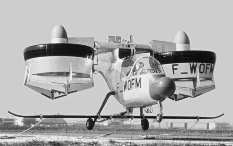
Pitch was obtained by moving both ducts together, yaw by tilting them differentially, with roll achieved by differentially varying propeller pitch. The Nord N500 was 6.7 meters (22 feet) long and had a span of 6.1 meters (20 feet); weight was 1,250 kilograms (2,760 pounds). After its initial flight, the first machine was put through wind-tunnel tests -- with the program canceled before the tests were completed, and the machine never flying again. It is unclear what happened to the two aircraft; presumably, they were scrapped.
* Nobody ever fielded a tiltduct heavier-than-air aircraft in the 20th century, though the technology was used on some modern airships. However, in the 21st Century, there has been interest in electric VTOL aircraft for short-range transport. Such machines need to be discussed in detail elsewhere -- but a Bell concept, the "Nexus 4EX", unveiled in 2020, is noteworthy here, because it was something of a revival of the Bell X-22.
The Nexus 4EX name indicated "4 tiltducts, purely electric (battery) power, experimental". The concept envisions a five-seat aircraft, with two tilting ducts, driven by electric motors, on the forward fuselage and two at the tips of an aft wing -- much like the X-22. Projected range is 100 kilometers (60 miles).

A "Nexus 6HX" had been announced in 2019, being similar but with six tiltducts, and hybrid propulsion -- that is, using a turbine or piston engine generator to provide electricity for the drive motors. Projected range was about 240 kilometers (150 miles). Bell envisioned a hybrid "Nexus 4HX" as well. Of course, the Nexus 6HX would have better hover capability than the Nexus 4EX -- all the more so because the 6HX design had longer ducts, improving hover efficiency, at the expense of more drag.
Bell has been an arm of the Textron group since 1960; in 2021, the project was transferred to another arm, Textron eViation (TeV), which has a mandate to develop electric aircraft. The hype over electric aircraft has faded -- practical problems, particularly battery capacity, have slowed development -- but TeV is still working towards a flight prototype of the Nexus 4EX.
BACK_TO_TOP* Tiltrotors were an obvious approach to VTOL flight; it was equally obvious to tilt the entire wing. The first known "tiltwing" design was conceived by one D.H. Kaplan, who had worked for the Piasecki helicopter company, and who set up the "Convertawings" firm to build the "Model B" tiltwing. It wasn't completed and never flew.
The Piasecki company -- which was renamed "Vertol" in 1956, to later become an arm of Boeing -- continued work on tiltwing technology. Also in 1956, the US Army and Navy awarded Vertol a contract to build a tiltwing demonstrator, with the company designation of "Model 76" and the military designation of "VZ-2A", or just "VZ-2". It performed its initial flight, in hover, on 13 April 1957. The VZ-2 was strictly a lashup, with:
The VZ-2 was 7.59 meters (24 feet 11 inches) long, had a wingspan of 8.05 meters (26 feet 5 inches), and had an empty weight of 1,135 kilograms (2,500 pounds).
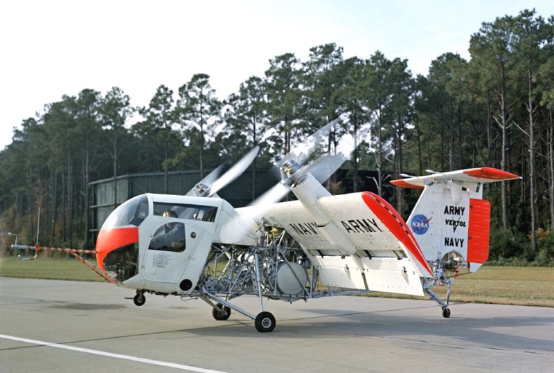
The VZ-2 remained in trials to 1964, performing hundreds of flights, including many complete transitions from vertical to horizontal and back again, with total flight time being over 450 hours. Problems uncovered included buffeting from gusty winds when the wing was in the vertical position, this being an inherent problem with tiltwings. The machine ended up in the hands of the Smithsonian Institution, but at last notice it wasn't on display.
* In 1957, a year after the VZ-2 program was initiated, the Air Force awarded a contract to the Hiller helicopter company to develop a prototype tiltwing transport aircraft. Initial flight of the "X-18A" was on 24 November 1959.
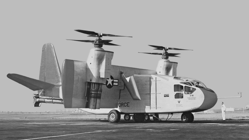
The X-18 was built around the fuselage of the Chase YC-122 twin-piston transport -- an ancestor of the Fairchild C-123 Provider transport. It had fixed tricycle landing gear, the nose gear with twin wheels, the main gear with single wheels. The tail assembly was of conventional configuration, the tailplane having a noticeably steep dihedral. It had three engines:
The YT40 turboprop was actually a "twin-pac" engine, being two coupled Allison YT38 turboprops, driving a contraprop assembly, with twin three-bladed props. The YT40 had originally been used for the notoriously unsuccessful Lockheed XFV-1 and Convair XFY-1 Pogo "tailsitter" VTOL fighter program.
There was no cross-coupling across the wing between the two engine assemblies. The duct through which the J34 turbojet exhausted ended in an up-down vent, with the exhaust directed appropriately to provide pitch control. Cockpit controls were much the same as for any prop transport aircraft of the era, except for addition of a wing-tilt lever control.
   ___________________________________________________________________

   HILLER X-18:
   ___________________________________________________________________

   wingspan:
     14.6 meters (47 feet 11 inches)
   length:
     19.2 meters (63 feet)
   height:
     7.5 meters (24 feet 7 inches)

   empty weight:
     12,150 kilograms (26,785 pounds)
   max take-off weight:
     14,970 kilograms (33,000 pounds)

   max speed:
     405 KPH (255 MPH / 220 KT)
   service ceiling:
     8,500 meters (35,300 feet)

   ___________________________________________________________________
The X-18 performed 20 flights in all to 1962, if never in vertical or hovering flight, though partial transitions were performed. The 20th flight nearly ended in disaster, when a prop suffered a pitch control anomaly at altitude, the aircraft going into a spin. The pilot regained control, but the aircraft never flew again.
The X-18 was used for ground tests to 1964, performing "flights" on a captive test rig. It was finally damaged in testing, and then scrapped. The program was judged successful, but partly in terms of uncovering errors: the lack of cross-shafting between the engines was judged a big mistake.
The Kaman company, a helicopter maker, also put together a tiltwing demonstrator, the "K-16B", under a US Navy contract. It was a Grumman Goose flying boat fitted with a tiltwing, featuring twin General Electric turboprops. It went through wind tunnel tests in 1962, but never actually flew. It appears the program simply ran out of steam.
BACK_TO_TOP* The 1961 Tri-Service VTOL Program led to a large tiltwing built -- following award of a contract in 1962 -- by a collaboration between Vought, Hiller, and Ryan, with the program managed by the Navy on behalf of all the armed services. The Hiller X-18 was used to evaluate technologies for the program.
The first of five "XC-142A" machines performed its initial flight, in horizontal mode, on 29 September 1964, with first flight transition on 11 January 1965. By that time, Vought had become part of the Ling-Temco-Vought (LTV) group, and so the machine was known as the "LTV XC-142A". Aircraft deliveries to the USAF were completed in 1966.
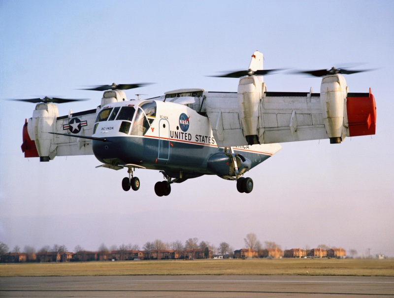
The XC-142, sitting on a runway, looked like a fairly conventional medium tactical transport aircraft. It had:
The only betraying details that the XC-142 was something out of the ordinary were a three-bladed rotor mounted horizontally behind the tail assembly, for pitch control; the short, tilting wings; and the oversized four-bladed fiberglass props on the T64s, with a diameter of 4.7 meters (15 feet 5 inches). The T64s were all cross-coupled to ensure safe engine-out operation, with the driveshaft system also feeding back to the horizontal tail rotor.
   ___________________________________________________________________

   LTV XC-142:
   ___________________________________________________________________

   wingspan:
     20.6 meters (67 feet 6 inches)
   wing area:
     49.67 sq_meters (534.5 sq_feet)
   length:
     17.71 meters (58 feet 1 inch)
   height:
     7.95 meters (26 feet 1 inch)

   empty weight:
     10,270 kilograms (22,595 pounds)
   max take-off weight:
     20,225 kilograms (44,500 pounds)

   max speed:
     695 KPH (430 MPH / 375 KT)
   service ceiling:
     7,620 meters (25,000 feet)
   operational radius:
     755 kilometers (470 miles / 410 NMI)
   ferry range:
     6,100 kilometers (3,800 miles / 3,300 NMI)

   ___________________________________________________________________
The XC-142 was much closer to an operational machine than related VTOL projects of the era; it could haul 3,335 kilograms (8,000 pounds) of cargo, or 32 troops, or 24 litters with four attendants. The five machines were run through extensive field tests from 1966 -- which proved somewhat troublesome, four of the five machines making heavy landings that caused damage, one killing three people.
The aircraft wasn't a dog; it was just that there were corner cases due to its VTOL capability that couldn't be easily foreseen, and could be dangerous. For example, the power cross-coupling of the engines didn't handle wing flex well, and handling at low speeds, in which the aircraft was in a flight regime midway between a fixed-wing aircraft and a rotorcraft, could be hazardous. It was also noisy and with high vibration levels, leading to crew fatigue, and inducing mechanical breakdowns. The high noise level would also attract unwanted attention on a battlefield, and there was no way to make the machine much quieter: the noisiness was inherent in the design.
Although the XC-142 could have been realistically put into service, the military decided against it. The major problem was that, as a hybrid of fixed-wing aircraft and rotorcraft, it was inferior to both in their own regimes, and there was no perceived niche for its unique capabilities that justified its relatively high cost. This was a problem that bedeviled early VTOL machines.
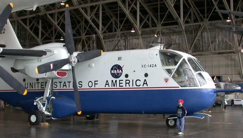
An XC-142 was shipped across the Atlantic in 1967 to put on a performance at the Paris Air Show that year; the crowd was suitably impressed, but nobody wanted to buy the thing. NASA conducted trials with one XC-142 up to 1970, when it was then handed over to the USAF Museum, where it is on display today. A commercial version, the "Downtowner", was considered, but was never more than a "paper plane".
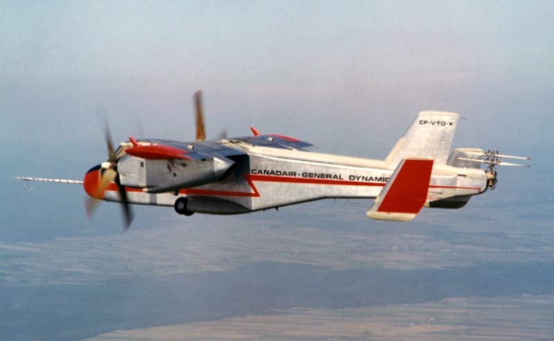
* The Canadair firm of Canada had investigated VTOL technology from 1956, with the company being awarded a contract from the Canadian Department of Defense in 1963 to construct a twin-engine tiltwing, the "CL-84 Dynavert", with the first of four machines performing its initial flight on 7 May 1965. It was called "Dynavert" because Canadair was a subsidiary of the US General Dynamics firm.
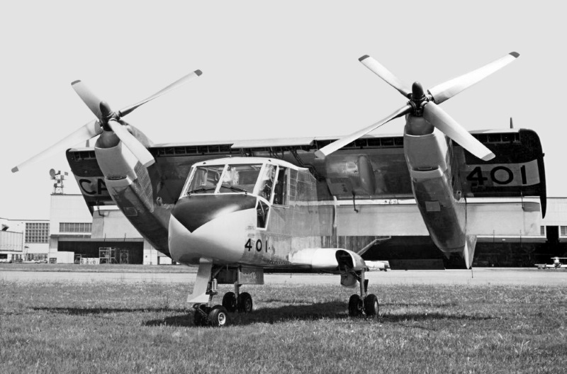
The CL-84 had broad configurational similarities to the XC-142, being a high-wing tiltrotor machine with a short rectangular wing and tricycle landing gear, all gear with dual wheels -- the nose gear retracting backwards, the main gear retracting forwards into sponsons -- and a horizontal rotor system on the extreme tail -- with twin two-bladed coaxial rotors that were locked into a fore-aft position in horizontal flight. The CL-84 was an entirely different aircraft from the XC-142, however:
Flight control arrangement was like that of a fixed-wing aircraft, the only unusual feature being a wing tilt switch. Both aircrew had zero-zero ejection seats. The CL-84 could haul 1,135 kilograms (2,500 pounds) of load in VTOL operation, with about 25% more payload when flown in a short take-off configuration, with the wings tilted 45 degrees. The CL-84 prototype was evaluated by the US Tri-Service program.
   ___________________________________________________________________

   CANADAIR CL-84:
   ___________________________________________________________________

   wingspan:
     10.46 meters (34 feet 4 inches)
   wing area:
     21.67 sq_meters (233.3 sq_feet)
   length:
     14.42 meters (47 feet 4 inches)
   height:
     4.34 meters (14 feet 3 inches)

   empty weight:
     3,820 kilograms (8,415 pounds)
   MTO weight (VTOL):
     5,710 kilograms (12,600 pounds)
   MTO weight (STOL):
     6,575 kilograms (14,500 pounds)

   max speed:
     515 KPH (320 MPH / 280 KT)
   range, max fuel VTOL:
     680 kilometers (420 miles / 365 NMI)

   ___________________________________________________________________
The original CL-84 prototype was lost in an accident in 1967, both aircrew safely ejecting. Three more machines, designated "CL-84-1", were ordered in 1968, these aircraft being closer to an operational spec; they had dual controls, better avionics fit, stores hardpoints, and an improved fuel system. The US Navy evaluated the CL-84 in 1972, flight tests including operations off the helicopter assault carrier USS GUAM. Weapons were also evaluated on the CL-84, with a promotional video showing one carrying and firing an SUU-11A/A 7.62-millimeter Gatling Minigun pod. One of the CL-84-1s was lost in an accident in 1973, both crew again ejecting safely.
General Dynamics released design concepts of the CL-84 in operational configurations -- for example, with a bugeye cockpit like that of the Grumman S-2 Tracker, roles including antisubmarine warfare, airborne early warning, and battlefield support. The US military wasn't interested. Some sources claim there was a bias against Canadian aircraft at work, but the US Army was very fond of De Havilland Canada aircraft like the Otter and Caribou. It seems more plausible that, as with the XC-142, the US armed forces could see the limitations of the VTOL configuration, but couldn't see any advantages worth the added expense. Attempts to peddle the CL-84 overseas didn't get any better response. Two of the CL-84s ended up in museums in Canada.
BACK_TO_TOP* Sources include:
I had to scavenge a lot of details from Wikipedia and elsewhere online.
* Illustrations details:
* Revision history:
   v1.0.0 / 01 apr 18
   v1.0.1 / 01 jun 19 / Illustrations update.
   v1.0.2 / 01 apr 21 / Added Bell Nexus 4EX.
   v1.0.3 / 01 mar 23 / Review & polish.
   v1.0.4 / 01 may 26 / Review & polish.
BACK_TO_TOP